Common Flashing Installation Errors and How to Prevent Building Leaks
Building envelope integrity depends fundamentally on the seamless integration of thin, impervious sheet materials engineered to redirect liquid water away from vulnerable structural joints. Flashing assemblies act as the primary defense mechanism at architectural material transitions, roof-to-wall intersections, window perimeters, and foundation sill plates. Common Flashing Installation Errors. While primary cladding systems absorb the brunt of severe weather exposure, water inevitably bypasses exterior siding, brick veneers, and roofing shingles. Once liquid water breaches the outer shell, correctly installed metal or synthetic flashing channels this moisture harmlessly back to the exterior environment.
When field mechanics execute flashing details incorrectly, the consequences remain hidden inside wall cavities for extended periods before manifesting as interior drywall staining or structural timber rot. Minor detailing mistakes, such as inverted horizontal laps or missing end dams, transform protective metal profiles into active water collection funnels. The dynamic nature of wind-driven rain, combined with capillary action and thermal expansion forces, ensures that any seam vulnerability becomes a focal point for chronic moisture intrusion. Structural framing member deterioration often advances silently behind intact siding panels, leading to costly structural remediation efforts.
Analyzing systemic installation mistakes requires evaluating the physical laws governing fluid dynamics, material compatibility, and structural movement tolerances. Waterproofing membranes and sheet metal flashings cannot be treated as isolated components; they function as integral elements within complex, multi-layered wall drainage systems. Preventing premature envelope degradation demands rigorous field oversight, adherence to gravity-lap principles, and an understanding of how disparate building materials interact over decades of environmental exposure.
Understanding “Common Flashing Installation Errors”
Defining Water Shedding Continuity
Examining common flashing installation errors reveals that failure modes stem predominantly from breaking water-shedding continuity rather than material defects. Flashing profiles must adhere strictly to the principle of drainage sequence, where each upper layer laps over the lower layer like traditional roof shingles. When installers accidentally tuck lower flashing legs beneath underlying weather-resistive barriers, gravity directs wind-driven rain straight into structural sheathing. This mechanical oversight invalidates expensive waterproofing membranes, turning protective wall systems into conduits for hidden decay.
Thermal Movement and Fastener Binding
Metal flashing profiles expand and contract significantly in response to ambient outdoor temperature fluctuations throughout changing seasons. Restraining long runs of copper, aluminum, or steel sheet metal with rigid, hard-pinned mechanical fasteners generates severe stress concentrations. Over time, restricted thermal movement buckles thin metal sheets, tears open sealed lap joints, and pulls fastener shanks clear out of wooden structural framing. Proper installations utilize sliding cleats or oversized fastener slots that accommodate cyclic expansion without compromising watertight seam integrity.
Galvanic Corrosion and Material Mismatches
Direct physical contact between dissimilar metals triggers rapid galvanic corrosion whenever rainwater creates an active electrolytic bridge across the junction. Placing mill-finish aluminum flashings in direct contact with wet pressure-treated lumber impregnated with copper salts leads to swift chemical pitting. Microscopic perforations form across aluminum sheets within short operational windows, permitting pressurized groundwater or rain to pass through undetected. Avoiding chemical degradation requires specifying compatible metals or placing heavy rubberized isolation tapes between reactive material surfaces.
Historical Context and Building Science Evolution
Traditional Heavy Lead and Solder Assemblies
Nineteenth-century masonry construction relied heavily on hand-formed thick lead, heavy copper plates, and custom-soldered sheet metal assemblies. Skilled metalsmiths meticulously crafted continuous step flashings, counter-flashings, and deep masonry cavity gutters that accommodated massive building movement without tearing apart. These historic mass-masonry structures lacked synthetic air barriers, relying instead on thick, permeable walls that dried out through natural thermal airflow.
Mid-Century Pre-formed Aluminum and Synthetic Rollouts
Post-war building booms introduced light, factory-extruded aluminum profiles alongside thin asphalt-impregnated felt papers to speed up residential housing construction. Installers abandoned traditional hand-soldered seams, relying instead on face-applied caulking compounds to seal critical metal overlap joints around window bucks. These early synthetic sealants degraded rapidly under intense solar ultraviolet exposure, leaving un-soldered lap seams wide open to driving rain intrusion.
Modern Self-Adhered Flexible Flashing Membranes
Contemporary envelope construction utilizes self-adhered rubberized asphalt, butyl, and synthetic acrylic flexible flashing membranes that mold around complex three-dimensional corners. Modern building codes require continuous weather-resistive barriers, rigid head flashings, and integrated pan flashings under all exterior window and door openings. Today, field quality depends on combining rigid sheet metal profiles with self-adhered membrane tapes to create redundant, long-lasting drainage paths.
Conceptual Frameworks and Hygrothermal Models
The Gravity Drainage Plane and Shingle-Lap Mechanics
Maintaining a continuous drainage plane relies on gravity-assisted water management, where higher components overlap lower components sequentially without exception. Understanding this fundamental geometric model prevents water from bypassing protective weather barriers around window perimeters, wall intersections, and roof valleys.
Gravity-Lap Geometry Rules
When horizontal flashing strips overlap lower membrane layers, liquid water flows downward over smooth exterior surfaces naturally. Reversing this sequence creates an upward-facing pocket that catches running water, driving moisture deep into internal wood wall framing.
Wind-Driven Pressure Equalization
High-velocity winds create air pressure differentials across wall cavities, forcing surface water upward over short vertical flashing legs. Incorporating tall vertical standing legs and back-hems on metal flashings prevents wind forces from pushing standing water over internal flashing boundaries.
Capillary Action and Surface Tension Dynamics
Water molecules draw themselves into microscopic gaps between closely spaced building materials through strong capillary action forces, defying gravity. Capillary draw pulls standing rainwater sideways through unsealed metal lap seams and upward between tightly stacked siding panels.
Capillary Break Architecture
Engineers prevent capillary migration by introducing wide air gaps or physical drip edges that interrupt fluid surface tension. Forming a sharp hemmed drip edge along lower metal flashing legs forces clinging water droplets to fall cleanly away from building walls.
Sealant Joint Spacing Controls
Pressing two sheet metal flashing surfaces tightly together without applying continuous butyl sealant creates ideal capillary channels for water movement. Maintaining recommended joint clearances or embedding elastomeric sealants breaks capillary bridges, preventing water from traveling through overlapping metal joints.
Material Classifications and Flashing Variations
Self-Adhered Flexible Bituminous Membranes
Rubberized asphalt flashing tapes provide excellent self-healing properties around mechanical fastener penetrations, making them popular for window pan installations. However, rubberized asphalt degrades rapidly when placed in direct contact with flexible polyvinyl chloride window flanges or high-temperature metal roofs.
Temperature Limit Thresholds
Standard rubberized asphalt tapes soften and bleed dark oils when exposed to elevated summer roof temperatures exceeding one hundred sixty degrees Fahrenheit. High-temperature synthetic acrylic or butyl formulations must be specified beneath dark metal flashings to prevent adhesive breakdown and sagging.
Substrate Priming Requirements
Self-adhered membranes fail to bond securely when applied over dusty concrete, oriented strand board, or cold structural sheathing panels. Applying compatible liquid primers consolidates surface dust, ensuring permanent chemical adhesion between flexible flashing tapes and rough substrate surfaces.
Pre-Formed Rigid Sheet Metal Profiles
Rigid sheet metal flashings made from stainless steel, painted aluminum, or galvanized copper-bearing steel form durable, rigid water channels around roof chimneys and wall step intersections. Rigid metal withstands intense solar UV rays and mechanical abrasion that would destroy flexible synthetic membranes over long exposure periods.
Thermal Expansion Coefficient Variances
Aluminum expands at twice the rate of stainless steel when exposed to identical temperature shifts across summer and winter seasons. Installers must incorporate expansion slip joints every ten feet along continuous aluminum head flashings to prevent severe buckling and oil-canning.
Solderability and Field Joining Constraints
Stainless steel and heavy copper profiles accept permanent hand-soldered lap joints, creating absolute, watertight chemical bonds across roof-to-wall transitions. Aluminum cannot be soldered under field conditions, requiring mechanical overlap joints sealed with high-performance polyurethane or polyether sealants.
| Flashing Classification | Chemical Composition | Primary Physical Advantage | Critical Field Application Risk |
| Self-Adhered Rubberized Asphalt | Polymer-Modified Bitumen | Self-sealing around nail shanks | Incompatibility with PVC & low heat resistance |
| Self-Adhered Butyl Membrane | Synthetic Butyl Adhesive | Broad temperature tolerance | Poor adhesion to dusty, un-primed masonry |
| Rigid Formed Aluminum | Extruded Mill/Painted Metal | UV-proof & lightweight strength | High thermal movement & galvanic corrosion |
| Stainless Steel Sheet | Grade 304/316 Steel | Exceptional life & solderable | Difficult to field-bend; high material cost |
Real-World Field Scenarios and Failure Analysis Common Flashing Installation Errors
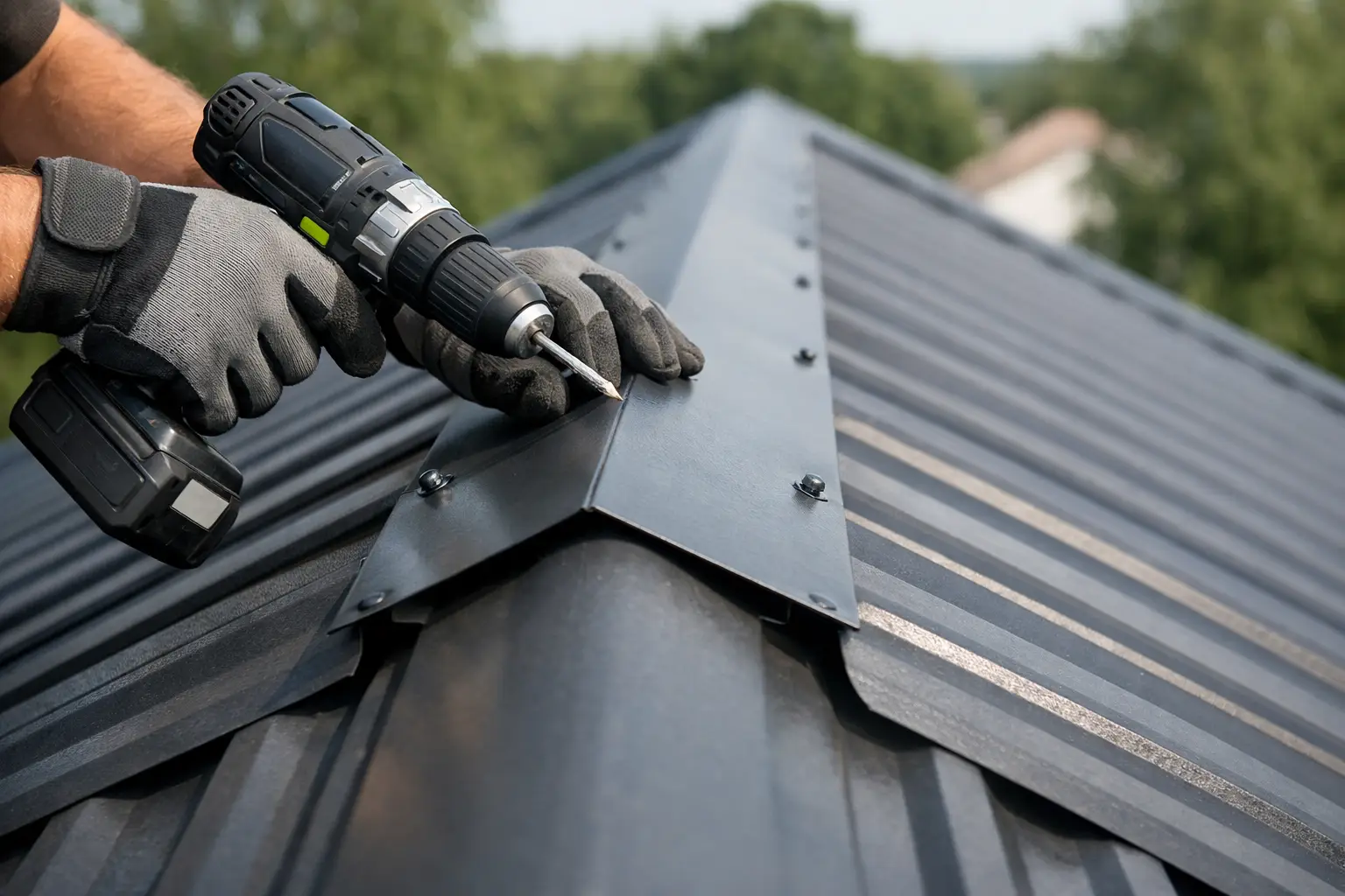
Missing Window Head Flashing End Dams
A multi-story commercial wood-frame residential complex experienced severe window header rot across its western elevation three years after completion. Field inspection revealed that rigid aluminum drip caps were installed over window openings without bending the profile ends upward into functional end dams.
Water Migration Path
Rainwater hitting the upper cladding flowed down onto the flat window head flashing, running horizontally toward the outer metal corners. Lacking vertical end dams, water spilled off the flashing ends directly behind vertical trim boards, saturating unprotected rough window framing bucks.
Corrective Field Detailing
Technicians removed exterior trim panels, installed custom soldered metal head flashings featuring 1-inch end dams, and integrated self-adhered membrane patches over the vertical end flaps.
Missing Kick-Out Flashing at Roof-to-Wall Intersections
A two-story suburban residence developed severe interior drywall mold growth and structural wall sheathing decay along a lower roof step-flashing line. Demolition of exterior stucco panels revealed that standard step flashing was installed along the roof edge, but the lowest flashing piece lacked a kick-out diverter.
Hydraulic Overload Mechanism
Concentrated rainwater flowing down the roof valley reached the wall termination, bypassing the straight bottom step flashing piece completely. Water channeled directly into the exterior wall cavity behind the stucco system, soaking wood wall studs and interior sheetrock.
Systemic Remediation Protocol
Contractors replaced rotted wall sheathing, applied a continuous self-adhered membrane layer, and retrofitted a pre-formed molded kick-out flashing diverter. The new kick-out profile directed roof runoff outward into the gutter system, isolating the wall assembly from concentrated water flows.
Financial Modeling and Resource Allocation
Initial Material Costs versus Post-Construction Remediation
Allocating adequate financial resources for high-grade flashing materials represents a tiny fraction of total building envelope construction budgets. Using low-grade materials or skipping critical flashing accessories saves negligible upfront capital while exposing property owners to immense remediation expenses if hidden leaks develop.
Labor Allocation and Detailing Quality Control
Achieving watertight flashing integration requires meticulous manual labor, precise metal folding, and careful substrate preparation around complex wall geometry. Skimping on labor hours during critical window framing or roof step flashing phases leads directly to premature envelope failures and structural decay.
| Cost Allocation Category | Budget Proportion | Primary Cost Drivers | Long-Term Envelope Return |
| Flashing Metals & Tapes | 15% – 25% | Stainless steel, butyl grade, pre-formed boots | Provides UV resistance & low-temperature seal |
| Substrate Prep & Priming | 20% – 30% | Surface cleaning, liquid primers, drying time | Guarantees permanent membrane chemical bond |
| Skilled Detailing Labor | 35% – 45% | Hand-folding end dams, soldering, custom fits | Eliminates water entry at complex 3D transitions |
| Quality Control Inspections | 10% – 15% | Water spray testing, electronic leak checks | Identifies hidden installation errors early |
Diagnostic Tooling and Execution Hardware
Diagnostic Equipment and Leak Locators
Pinpointing hidden flashing installation errors before interior finishes sustain severe water damage requires specialized non-destructive testing tools. Calibrated water spray racks apply pressurized water streams across window perimeters, simulating storm conditions to expose unsealed lap joints quickly.
Specialized Installation Hand Hardware
Executing durable, professional flashing installations demands specialized hand tools designed to shape metal profiles cleanly without cracking protective painted coatings. Hand-seamers and sheet metal notches enable field mechanics to fold crisp vertical end dams and drip edges directly on jobsite staging platforms.
-
Heavy-duty hand seamers for bending custom vertical end dams on rigid metal head flashings
-
Pneumatic cap-staplers designed to secure weather barriers without tearing underlying synthetic wraps
-
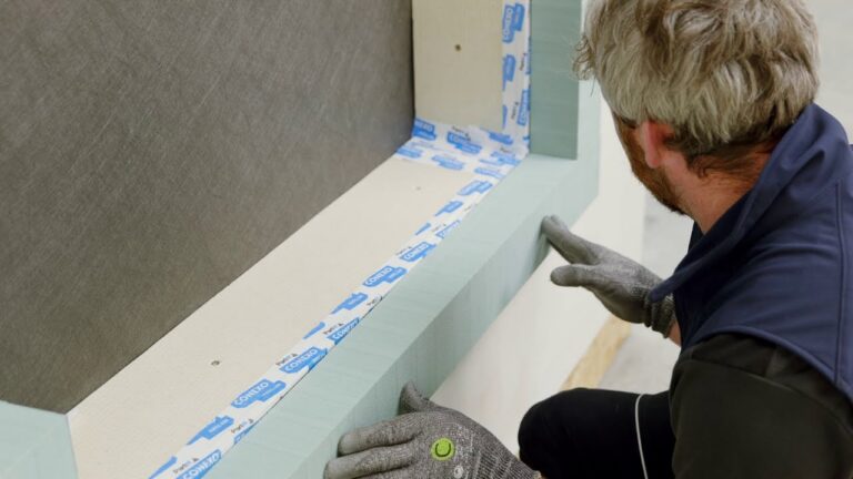
High-tack weighted seam rollers to press self-adhered flashing tapes firmly into rough sheathing
-
Infrared thermal imaging cameras to locate saturated wall insulation and cold air leaks behind siding
-
Moisture meters with insulated long pins to measure wood sheathing moisture content through trim gaps
-
Calibrated water spray rack systems engineered to conduct AAMA window leak field tests
-
Non-corrosive hand notchers for cutting precise expansion slots in continuous aluminum flashings
Comprehensive Risk Taxonomy and Degradation Pathways
Reverse Lap Geometry and Water Trapping
Installing upper weather-resistive barriers beneath lower flashing metal legs forms severe reverse lap conditions that catch running water. Gravity channels intruding rainwater directly behind protective membranes, saturating wood sheathing panels and accelerating structural decay.
Sealant Dependency and Chemical Breakdown
Relying entirely on surface-applied caulking tubes to bridge gaps across misaligned metal flashing joints leads to rapid joint failure. Solar ultraviolet radiation degrades organic elastomeric sealants within short timeframes, leaving open joint gaps exposed to driving rain.
Thermal Fatigue and Fastener Back-Out
Repeated daily expansion and contraction cycles subject hard-pinned metal flashings to extreme thermal fatigue stresses over time. Cyclic metal movement enlarges fastener hole openings, loosens mechanical screws, and tears open sealed sheet metal lap seams.
Governance Protocols and Long-Term Adaptation
Pre-Cladding Flashing Verification Audits
Preventing flashing errors requires establishing strict quality control sign-off protocols before trade crews enclose wall assemblies with exterior cladding. Inspectors must verify that all window head flashings feature functional end dams, proper shingle-lapping, and compatible self-adhered membrane patches.
Scheduled Envelope Maintenance Inspections
Facility management teams must execute structured annual visual inspections across building envelopes, focusing on high-stress material transition zones. Clearing accumulated leaves from roof step flashings and checking perimeter counter-flashing sealants prevents standing water from stressing sealed joints.
-
Inspect roof-to-wall step flashings to ensure clear water flow paths into gutters.
-
Examine window head flashing drip edges for physical damage, paint peeling, or sealant failure.
-
Verify kick-out flashing diverters remain unblocked by roof moss or organic leaf debris.
-
Check counter-flashing mortar reglets along brick chimneys for cracking or mortar loss.
-
Inspect foundation sill flashings to ensure weep holes remain completely unobstructed.
-
Re-apply high-performance polyurethane sealants along exposed trim counter-flashing joints showing weathering.
Diagnostic Metrics and Envelope Evaluation
Field Water Infiltration Spray Testing
Evaluating window and wall flashing integrity involves conducting standardized field water spray tests in accordance with ASTM and AAMA testing protocols. Technicians apply pressurized water jets against flashing transitions while monitoring interior framing surfaces for early water droplets.
Quantitative Wood Sheathing Moisture Tracking
Monitoring internal wood framing health requires recording moisture content percentages using calibrated resistance-based moisture meters across wall intersections. Wood sheathing moisture levels must remain below sixteen percent to eliminate wood-decay fungus growth risks inside enclosed cavities.
Digital Quality Control Record Archiving Common Flashing Installation Errors
Project management teams should maintain digital jobsite logs containing high-resolution photographs of all concealed flashing assemblies before covering them with siding. Storing detailed installation photos simplifies troubleshooting if unexpected leaks emerge decades later during severe storm events.
Persistent Industry Misconceptions
The Caulk Replaces Flashing Fallacy
A dangerous construction myth assumes that applying generous beads of high-grade silicone caulk eliminates the need for sloped metal flashings. Caulking compounds function strictly as secondary air and water seals, failing rapidly when forced to resist standing water without structural flashing backing.
The Self-Healing Membrane Infallibility Myth
Inexperienced installers often assume self-adhered asphalt flashing tapes seal around any mechanical fastener under all jobsite conditions. While rubberized asphalt seals around smooth nail shanks, heavy screw threads, grouped staples, or angled fasteners create gaps that leak water.
The Universal Metal Compatibility Misconception
Many field mechanics believe any corrosion-resistant metal can be safely placed in direct contact with other metals without structural risk. In reality, pairing aluminum with copper or stainless steel with mild carbon steel triggers rapid galvanic reaction cells that destroy metal sheets.
The Flat Head Flashing Adequacy Fallacy
Installing completely flat metal drip caps over window frames without forming a outward slope allows standing water to pool along horizontal edges. Standing water eventually backs up under vertical siding laps through capillary draw, saturating exterior sheathing and window headers.
Ethical and Practical Considerations
Occupant Health and Environmental Protection
Failing to install proper flashing profiles allows hidden moisture accumulation inside wall stud cavities, fostering toxic mold colony growth. Prioritizing correct flashing execution protects indoor air quality, preventing severe respiratory health problems for building residents over long-term occupation.
Construction Waste Minimization and Sustainability
Replacing water-damaged structural framing and decayed sheathing prematurely generates massive volumes of construction debris that fill local municipal landfills unnecessarily. Installing durable, correctly detailed metal flashings extends building lifespans, preserving valuable natural forestry resources over multi-generational operational windows.
Conclusion
Understanding common flashing installation errors requires combining sound fluid dynamics, material chemistry knowledge, and disciplined field craftsmanship. Protecting building envelopes depends on maintaining continuous shingle-lapped drainage planes, incorporating vertical end dams on head flashings, and accommodating thermal metal movement. Construction teams that enforce rigorous pre-cladding inspections and honor basic gravity drainage principles create resilient, dry structures that withstand environmental exposure across changing seasons.